bluepill-from-scratch: 01.5-blinkasm
01.5-blinkasm
tl;dr
full source here.
assemble:
arm-none-eabi-as blink.s -o blink.olink:
arm-none-eabi-ld -T link.ld blink.o -o blink.elfflash:
./flash.exp blink.elffrom scratch
Our goal is to write a program in assembly which blinks the LED connected to PC13 of our STM32F103C8T6.
First, we need to know which assembler to use. We’ll stick with GNU
tools, chiefly arm-none-eabi-as and
arm-none-eabi-ld. This is important information for writing
our assembly, as it directly affects the code we write.
“Assembly” is just any low-level programming language which closely resembles the direct use of a CPU architecture’s hardware-level instruction set. It provides syntax that corresponds to instruction encodings, because typing out each instruction bitfield in binary by hand would be an egregious waste of time. We need an assembler to translate the syntax into instruction encodings and do other convenient things.
The next step is to identify our CPU and therefore our architecture/ISA. The STM32F103 microcontroller in our bluepill uses an ARM Cortex-M3 CPU. According to the Cortex-M3 reference manual [1], it uses the ARMv7-M architecture which uses a subset of the Thumb-2 ISA. The Thumb-2 ISA is what we’re interested in.
Introduced with the ARMv6T2 architecture [2], Thumb-2 is an extension of the pre-UAL 16-bit-only instruction width Thumb ISA. Thumb-2 allows the use of both 16-bit and 32-bit instruction widths, with the idea being to combine code density and performance. With its introduction came the Unified Assembler Syntax (UAL), which provides a single assembly syntax (i.e., the mnemonic and operands of each instruction) to supersede the previous separate syntaxes of the ARM ISA (32-bit) and Thumb ISA (16-bit). The assembler then translates the UAL syntax into the appropriate operations for either Thumb or ARM, or returns errors when an operation is unsupported.
With this information, we write the first three lines of our code. These are GNU Assembler ARM-dependent directives [3][4].
.syntax unified
.cpu cortex-m3
.thumb
.syntax unified tells GNU assembler that we’re using the
ARM UAL, and .thumb tells GNU assembler that our CPU
supports mixed 16-bit and 32-bit instruction widths, instead of the
fixed 32-bit .arm ISA. The directive
.cpu cortex-m3 specifies our target processor, so that the
assembler may recognize unsupported instructions for this core and issue
errors at the time of assembly. Otherwise, it defaults to a permissive
mode where certain .thumb instructions that we don’t
support are encoded anyways, resulting in hardfaults at run-time. In our
case we only use base Thumb-2 instructions, so it isn’t absolutely
necessary here.
You might be wondering why the directive isn’t something like
.thumb-2. This is because in the context of post-UAL assembly, Thumb-2 essentially replaces the old Thumb which used to refer to 16-bit only instructions, such that Thumb now refers to the new mixed 16-bit/32-bit instruction set [5]. ARM Holdings likes to make stuff as confusing as possible.
With the hard part out of the way (navigating ARM terminology) , we can start writing the actual code. We’ll start with the vector table and the four entries necessary to start running code.
.section .vectors
    .word 0x20005000
    .word reset_handler + 1
    .word nmi_handler + 1
    .word hardfault_handler + 1
The assembler directive .section places the following
.word values into an input section labeled
.vectors, which we know our linker script is looking for.
This ensures it is placed predictably at the very beginning of the
.text output section – and thus the flash – where the
Cortex-M3 can find it, regardless of where in the assembly the vector
table is defined. The indentation is purely cosmetic.
0x20005000 is the top of our stack. The hardware needs
this value in order to know where to start growing the stack downwards.
The top of our stack is also the last byte of RAM. Top of stack = end of
ram = RAM start + RAM size = 0x20000000 + 20KB = 0x20000000 + 0x5000 =
0x20005000.
The other three values are the addresses of the interrupt handlers
considered the bare-minimum in order for the core to start executing
code. reset_handler is our code entry point, called upon..
reset. nmi_handler (Non-Maskable Interrupt) is needed for
serious external failures like power loss, and
hardfault_handler is needed here for every other type of
fault [6], most commonly something like an
invalid memory access. The processor triggers these handlers so that we
stop running application code when something bad happens and can thus do
what we need to do before all hell breaks loose, like gracefully shut
down or gather valuable debugging information. With these three
handlers, the processor is satisfied.
Why are we adding 1 to the handler addresses? It has to do with
interworking, which is the ability to switch between ARM (32-bit only)
and Thumb (16/32-bit) execution mid-program for performance/code-size
reasons. To accommodate this, some instructions which branch to code
must use the LSB of the address to denote whether the code being
branched to should be executed as Thumb or ARM code, where
1 = Thumb , and 0 = ARM [7][8][9]. Addresses used in these instructions
are called “interworking addresses”. It seems vector addresses also
classify as interworking addresses. In the case of Thumb-only processors
like the Cortex-M3, a UsageFault will be generated if bit[0] of any
interworking address is not 1, which is why we add 1 to set the handler
LSBs. You might be wondering why we need to tell a Thumb-only processor
that we are executing Thumb code. For consistency, I guess.
We then switch back to placing code in the .text input
section, which is where program code normally goes without any
directives.
.section .textWith that, we start defining functions. Officially these are called labels, as all they really do is attach a name to an address for our convenience.
nmi_handler:
    b nmi_handler

hardfault_handler:
    b hardfault_handler
Here we simply define nmi_handler and
hardfault_handler as infinite loops, as we did in C. We
just use b because we are branching unconditionally and
don’t care about linking.
.global reset_handler
reset_handler:
We use the .global directive for
reset_handler so that the linker script can find it for the
ENTRY() command. Functions are static/local by default in
assembly.
    ldr  r0, =0x40021018  @ RCC_APB2ENR
    ldr  r1, [r0]
    orr  r1, #0x10        @ set bit 4 (IOPCEN)
    str  r1, [r0]
Here we load the address for RCC_APB2ENR as a constant
using ldr = , then access the contents of that address,
reading them into r1. We set bit 4 with a bitwise
orr to enable the clock for GPIO port C. We then write the
modified contents back into RCC_APB2ENR with
str.
Our first instruction here
(ldr <reg>, =<expression>) is a
“psuedo-instruction”, in that it’s sort of a placeholder that gets
translated by the assembler into a different instruction. It isn’t
defined as a single instruction by either the ARM Cortex-M3 or ARMv7-M
reference manuals. Instead, it’s defined by the assembler, here [10] for GNU and here [11] for armasm. It’s useful in that it
automatically gets translated into the most efficient single instruction
for loading any constant, either into a mov or
movw if the constant fits in the instruction, or into an
ldr Rd, [PC, #offset] by creating a literal pool
(.word) for the constant and calculating the PC offset for
referencing the literal pools. Without the assembler, this process would
be tedious and error-prone. We could also do something like:
.equ    RCC_APB2ENR, 0x40021018

    movw    r0, #:lower16:RCC_APB2ENR
    movt    r0, #:upper16:RCC_APB2ENR
which should be faster, but I chose to target smaller code size with
ldr = [12] .
The next section is very similar.
    ldr  r0, =0x40011004  @ GPIOC_CRH
    ldr  r1, [r0]
    orr  r1, #0x100000    @ set bit 20
    str  r1, [r0]
We do the same thing here for GPIOC_CRH, setting bit 20
to enable output mode for PC13.
If you’re wondering how we fit that huge 21-bit immediate into the
32-bit orr instruction, it’s because the constant is
encoded in such a way that it gets broken down into a constant and a
rotate right value, such that even 32-bit immediates may fit into only
12 instruction bits. Not all 32-bit values can be encoded this way, as
it only fits values that can be constructed by taking an 8-bit value and
rotating it by a 5-bit (0-31) value. It works well for setting bits and
bitfields 8-bits wide or less that are shifted some amount, but a value
like 0x12345678 for example cannot be encoded this way. The
exact logic is described in psuedocode by the ARMv7-M reference
manual:
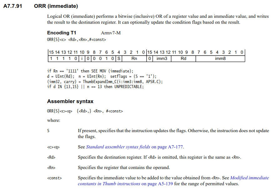
ORR
As you can see, the immediate is encoded into
i:imm3:imm8and passed to the functionThumbExpandImm_C().(imm32, carry) = ThumbExpandImm_C(i:imm3:imm8, APSR.C);Here’s the logic for
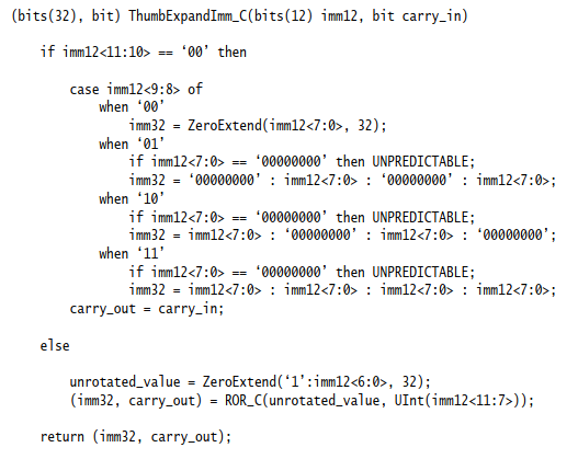
ThumbExpandImm_C().
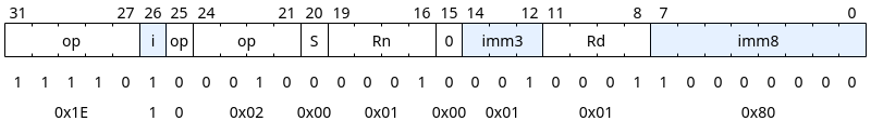
To demonstrate, I’ll skip ahead and grab the disassembly of our
orrinstruction, which will have the full instruction encoding that the assembler generated.f441 1180 orr.w r1, r1, #1048576 @ 0x100000Converting the instruction encoding
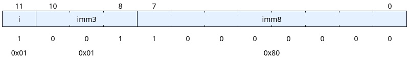
0xf441 1180into binary, we can see the values fori,imm3, andimm8:
and if we create
imm12from these bitfields,
we can plug it into
ThumbExpandImm_C(imm12, carry_in)to get:ROR_C(0x80, 19)A.k.a., rotate right
0x80by19bits. This is also known as a circular right shift.00000000000000000000000010000000 Rotate Right >> 19 -------------------------------- 00000000000100000000000000000000 = 0x100000 = 1048576 = (1 << 20)And thus, we get our original 21-bit immediate for
(1 << 20).Fortunately, the assembler generates these encodings for us.
With RCC and GPIOC configured, it’s time to blink the LED.
    ldr  r2, =0x4001100C  @ GPIOC_ODR

main_loop:
Here we load the address of GPIOC_ODR into
r2 and enter our main_loop.
main_loop:

    ldr  r1, [r2]
    orr  r1, #0x2000      @ set bit 13 (turn off LED)
    str  r1, [r2]
    ldr  r0, =500000      @ delay cntr = 500000

delay_1:
    subs r0, #1
    bne  delay_1

    ldr  r1, [r2]
    bic  r1, #0x2000        @ clear bit 13 (turn on LED)
    str  r1, [r2]
    ldr  r0, =50000         @ reset delay cntr to 50000

delay_2:
    subs r0, #1
    bne  delay_2

    b    main_loop          @ repeat
In our main_loop, we set PC13, delay, clear PC13, delay,
and repeat.
The s suffix in subs means that the
instruction updates the flags, including the Zero (Z) flag, which
bne checks before branching. It loops until r0
is 0.
We also set the delay counter for delay_2 to be 10x
shorter, just to distinguish it from our prior blink programs written in
C.
Now it’s time to see if we really get a blinking LED.
Assemble,
arm-none-eabi-as blink.s -o blink.olink,
arm-none-eabi-ld -T STM32F103C8T6.ld blink.o -o blink.elfand flash:
./flash.exp blink.elf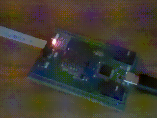
Heck yea.
It’d be kinda fun to see if we made any improvements in code size, so let’s compare:
[01-blinkasm]$ arm-none-eabi-size blink.elf
   text	   data	    bss	    dec	    hex	filename
     92	      0	      0	     92	     5c	blink.elf

[02-blink]$ arm-none-eabi-size blink.elf
   text	   data	    bss	    dec	    hex	filename
     88	      0	      0	     88	     58	blink.elf
Damn.. 4 extra bytes compared to the same program written in C and
compiled with -Os. I guess we’ll let GCC write the assembly
from now on.
If you’re curious, the following tab dives into the disassemblies to show how they saved those 4 bytes.
comparison
arm-none-eabi-objdump -d blink.elfblink.c disassembly
#################
## blink.c (-Os)
#################

blink.elf:     file format elf32-littlearm


Disassembly of section .text:

08000000 <vector_table>:
 8000000:	00 50 00 20 15 00 00 08 11 00 00 08 13 00 00 08     .P. ............

08000010 <nmi_handler>:
 8000010:	e7fe      	b.n	8000010 <nmi_handler>

08000012 <hardfault_handler>:
 8000012:	e7fe      	b.n	8000012 <hardfault_handler>

08000014 <reset_handler>:
 8000014:	4a0d      	ldr	r2, [pc, #52]	@ (800004c <reset_handler+0x38>)
 8000016:	6993      	ldr	r3, [r2, #24]
 8000018:	f043 0310 	orr.w	r3, r3, #16
 800001c:	6193      	str	r3, [r2, #24]
 800001e:	4b0c      	ldr	r3, [pc, #48]	@ (8000050 <reset_handler+0x3c>)
 8000020:	685a      	ldr	r2, [r3, #4]
 8000022:	f442 1280 	orr.w	r2, r2, #1048576	@ 0x100000
 8000026:	605a      	str	r2, [r3, #4]
 8000028:	68da      	ldr	r2, [r3, #12]
 800002a:	f442 5200 	orr.w	r2, r2, #8192	@ 0x2000
 800002e:	60da      	str	r2, [r3, #12]
 8000030:	4a08      	ldr	r2, [pc, #32]	@ (8000054 <reset_handler+0x40>)
 8000032:	bf00      	nop
 8000034:	3a01      	subs	r2, #1
 8000036:	d1fc      	bne.n	8000032 <reset_handler+0x1e>
 8000038:	68da      	ldr	r2, [r3, #12]
 800003a:	f422 5200 	bic.w	r2, r2, #8192	@ 0x2000
 800003e:	60da      	str	r2, [r3, #12]
 8000040:	4a04      	ldr	r2, [pc, #16]	@ (8000054 <reset_handler+0x40>)
 8000042:	bf00      	nop
 8000044:	3a01      	subs	r2, #1
 8000046:	d1fc      	bne.n	8000042 <reset_handler+0x2e>
 8000048:	e7ee      	b.n	8000028 <reset_handler+0x14>
 800004a:	bf00      	nop
 800004c:	40021000 	.word	0x40021000
 8000050:	40011000 	.word	0x40011000
 8000054:	0007a120 	.word	0x0007a120
blink.s disassembly
#################
## blink.s
#################

blink.elf:     file format elf32-littlearm


Disassembly of section .text:

08000000 <nmi_handler-0x10>:
 8000000:	20005000 	.word	0x20005000
 8000004:	08000015 	.word	0x08000015
 8000008:	08000011 	.word	0x08000011
 800000c:	08000013 	.word	0x08000013

08000010 <nmi_handler>:
 8000010:	e7fe      	b.n	8000010 <nmi_handler>

08000012 <hardfault_handler>:
 8000012:	e7fe      	b.n	8000012 <hardfault_handler>

08000014 <reset_handler>:
 8000014:	480d      	ldr	r0, [pc, #52]	@ (800004c <delay_2+0x8>)
 8000016:	6801      	ldr	r1, [r0, #0]
 8000018:	f041 0110 	orr.w	r1, r1, #16
 800001c:	6001      	str	r1, [r0, #0]
 800001e:	480c      	ldr	r0, [pc, #48]	@ (8000050 <delay_2+0xc>)
 8000020:	6801      	ldr	r1, [r0, #0]
 8000022:	f441 1180 	orr.w	r1, r1, #1048576	@ 0x100000
 8000026:	6001      	str	r1, [r0, #0]
 8000028:	4a0a      	ldr	r2, [pc, #40]	@ (8000054 <delay_2+0x10>)

0800002a <main_loop>:
 800002a:	6811      	ldr	r1, [r2, #0]
 800002c:	f441 5100 	orr.w	r1, r1, #8192	@ 0x2000
 8000030:	6011      	str	r1, [r2, #0]
 8000032:	4809      	ldr	r0, [pc, #36]	@ (8000058 <delay_2+0x14>)

08000034 <delay_1>:
 8000034:	3801      	subs	r0, #1
 8000036:	d1fd      	bne.n	8000034 <delay_1>
 8000038:	6811      	ldr	r1, [r2, #0]
 800003a:	f421 5100 	bic.w	r1, r1, #8192	@ 0x2000
 800003e:	6011      	str	r1, [r2, #0]
 8000040:	f24c 3050 	movw	r0, #50000	@ 0xc350

08000044 <delay_2>:
 8000044:	3801      	subs	r0, #1
 8000046:	d1fd      	bne.n	8000044 <delay_2>
 8000048:	e7ef      	b.n	800002a <main_loop>
 800004a:	0000      	.short	0x0000
 800004c:	40021018 	.word	0x40021018
 8000050:	40011004 	.word	0x40011004
 8000054:	4001100c 	.word	0x4001100c
 8000058:	0007a120 	.word	0x0007a120
First of all, while looping they used 2
nopinstructions to our 0, which means they’re starting from a 4-byte deficit and need to otherwise save 8 bytes.They saved 4 bytes here by using offsets instead of 2 separate words,
8000050:	40011000 	.word	0x40011000

vs.

8000050:	40011004 	.word	0x40011004
8000054:	4001100c 	.word	0x4001100c
They saved 2 bytes here by re-using the GPIOC register and adding the offset instead of defining a separate register
 8000028:	68da      	ldr	r2, [r3, #12]
 800002a:	f442 5200 	orr.w	r2, r2, #8192	@ 0x2000

vs.

 8000028:	4a0a      	ldr	r2, [pc, #40]	@ (8000054 <delay_2+0x10>)

 800002a <main_loop>:
 800002a:	6811      	ldr	r1, [r2, #0]
 800002c:	f441 5100 	orr.w	r1, r1, #8192	@ 0x2000
And finally they saved another 2 bytes here when our
ldr =got translated into amovwinstruction, which is 32 bits wide.8000040: 4a04 ldr r2, [pc, #16] @ (8000054 <reset_handler+0x40>) vs. 8000040: f24c 3050 movw r0, #50000 @ 0xc350This happened because we used 50,000 instead of 500,000 for the second delay. 500,000 was already defined for the first delay, so
blink.cwas able to just re-use that.wordvalue with a 16-bitldrinstruction. Ourblink.son the other hand had to define both 500,000 as a.wordand 50,000 as an immediate within a 32-bitmovwinstruction.Those are the 8 bytes!
Also, if you were curious about this instruction, it’s to align the upcoming
.wordvalues to 4 bytes. GCC did it with anop.800004a: 0000 .short 0x0000When we applied the first 2 changes and saved 6 bytes, we automatically saved another 2 bytes when our literal pools happened to get word-aligned, removing the need for the 16-bit, 2 byte
.shortdirective. So, we saved the 8 bytes without sacrificing our distinguishing asymmetrical blink delay!Here’s our program with those 8 bytes reclaimed if you’re interested:
blink.s
.syntax unified
.cpu cortex-m3
.thumb

.section .isr_vector
    .word 0x20005000
    .word reset_handler + 1
    .word nmi_handler + 1
    .word hardfault_handler + 1

nmi_handler:
    b nmi_handler

hardfault_handler:
    b hardfault_handler

.global reset_handler
reset_handler:

    ldr  r0, =0x40021018     @ RCC_APB2ENR
    ldr  r1, [r0]
    orr  r1, #0x10           @ set bit 4 (IOPCEN)
    str  r1, [r0]

    ldr  r0, =0x40011004     @ GPIOC_CRH
    ldr  r1, [r0]
    orr  r1, #0x100000       @ set bit 20 (output 10MHz, open-drain)
    str  r1, [r0]

main_loop:
    ldr  r1, [r0, #8]        @ GPIOC_ODR 0x4001100C
    orr  r1, #0x2000         @ set bit 13 (turn off LED)
    str  r1, [r0, #8]
    ldr  r1, =500000         @ delay cntr = 500000

delay_1:
    subs r1, #1
    bne  delay_1

    ldr  r1, [r0, #8]
    bic  r1, #0x2000        @ clear bit 13 (turn on LED)
    str  r1, [r0, #8]
    ldr  r1, =50000         @ reset delay cntr to 50000

delay_2:
    subs r1, #1
    bne  delay_2

    b    main_loop          @ repeat
[samu@yoga 01-blinkasm]$ arm-none-eabi-size blink.elf text data bss dec hex filename 84 0 0 84 54 blink.elf
If we wanted to make our program and linker script as minimal as possible, we can forego the separate input section for the vector table and rely on defining it at the top of our assembly code.
An absolutely minimal script/assembly combination would look like the following:
minblink
/* minlink.ld */

SECTIONS
{
    . = 0x8000000;
    .text :
    {
        *(.text)
    }
}
/* minblink.s */ .syntax unified .thumb .word 0x20005000 .word reset_handler + 1 .word nmi_handler + 1 .word hardfault_handler + 1 nmi_handler: b nmi_handler hardfault_handler: b hardfault_handler reset_handler: ldr r0, =0x40021018 @ RCC_APB2ENR ldr r1, [r0] orr r1, #0x10 @ set bit 4 (IOPCEN) str r1, [r0] ldr r0, =0x40011004 @ GPIOC_CRH ldr r1, [r0] orr r1, #0x100000 @ set bit 20 (output 10MHz, open-drain) str r1, [r0] main_loop: ldr r1, [r0, #8] @ GPIOC_ODR 0x4001100C orr r1, #0x2000 @ set bit 13 (turn off LED) str r1, [r0, #8] ldr r1, =500000 @ delay cntr = 500000 delay_1: subs r1, #1 bne delay_1 ldr r1, [r0, #8] @ GPIOC_ODR 0x4001100C bic r1, #0x2000 @ clear bit 13 (turn on LED) str r1, [r0, #8] ldr r1, =50000 @ reset delay cntr to 50000 delay_2: subs r1, #1 bne delay_2 b main_loop @ repeat
That about does it.
It was fun, but I think I’ll stick with C.
references
[3] https://sourceware.org/binutils/docs/as/ARM-Directives.html
[4] https://sourceware.org/binutils/docs/as/ARM_002dInstruction_002dSet.html
[8] https://developer.arm.com/documentation/ddi0337/h/programmers-model/exceptions?lang=en
[9] https://developer.arm.com/documentation/ddi0403/ee/?lang=en (A4.1.1)
[10] https://sourceware.org/binutils/docs/as/ARM-Opcodes.html


